
- New
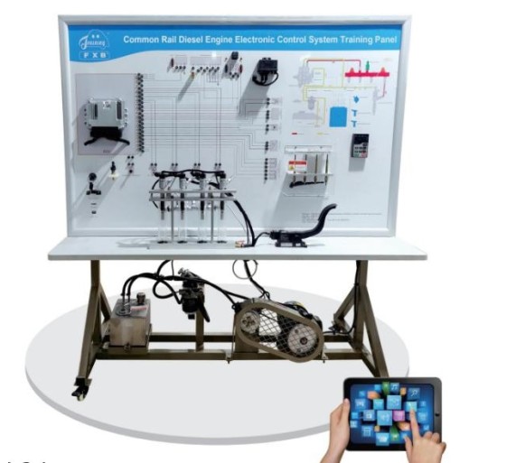
Reference : FXB-A21001 Common Rail Diesel Engine Electronic Control System Training Panel
The FXB-A21001 training panel is designed for learning, studying and diagnosing electronic control systems used in Common Rail diesel engines. Based on a Bosch-type engine management architecture, it incorporates real components to demonstrate the operation of sensors, actuators, the engine control unit (ECU) and the high-pressure fuel injection circuit.
Equipped with measurement terminals, an OBD-II diagnostic interface and an intelligent fault-setting and assessment system, this training panel enables learners to develop practical skills in signal analysis, electronic diagnostics and fault finding. It is suitable for technical schools, vocational training centres and institutions specialising in automotive maintenance.
The FXB-A21001 is an educational training unit designed for studying and maintaining electronic control systems used in Common Rail diesel engines. It incorporates real components from a Bosch-type engine management system to demonstrate the system architecture, component interactions and operating principles.
The training panel is suitable for secondary and higher technical education institutions, vocational training centres and organisations providing specialised training in automotive mechanics, diesel injection and electronic diagnostics.
The training panel is supplied with the following main components:
The training panel is supplied with an English user manual covering equipment introduction, operating procedures, fault configuration and troubleshooting methods. The interface and supplied system language is English.
The exact component configuration, diagnostic functions, immobiliser simulation capabilities and electrical or mechanical specifications should be confirmed in the manufacturer’s technical documentation. Compatibility with diagnostic tools depends on the installed ECU and the protocols supported.

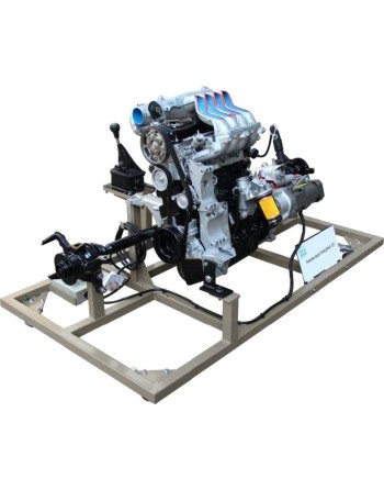
Reference : FXB-D01002 Gasoline Engine and Manual Transmission Cutaway Training Model
The FXB-D01002 training model, based on the transmission system of a Volkswagen Jetta, is designed for theoretical and practical automotive mechanics training. Its cutaway design allows learners to observe internal components and understand the operation of a manual transmission with 5 forward gears and 1 reverse gear. Driven by a single-phase gear reduction motor, the mechanism operates at low speed to facilitate observation of the power flow and gear operation. The training bench also features a protective cover for the drive components and a dedicated support for transmission disassembly exercises.
The model supports the following educational activities:
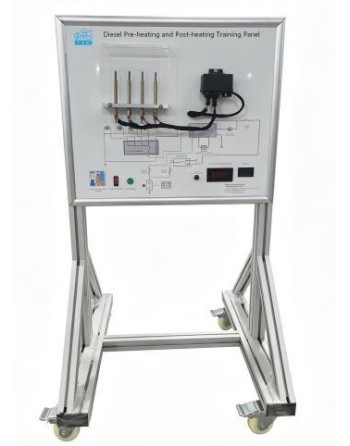
Reference : FXB-A21002 Diesel Engine Preheating and Postheating Training Panel
The FXB-A21002 training panel is designed for studying, demonstrating, and diagnosing diesel engine preheating and postheating systems. Based on a diesel engine configuration, it enables learners to analyze the operating cycles of glow plugs, the glow plug relay, and the electronic control module. Equipped with electrical measurement terminals and a fault simulation system, it allows trainees to perform measurements, identify malfunctions, and conduct diagnostic exercises under different engine temperature conditions. It is suitable for technical education institutions, vocational training centers, and automotive maintenance laboratories.
The FXB-A21002 training panel is particularly suitable for training courses covering:
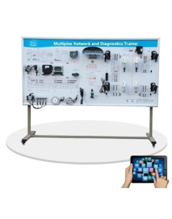
Reference : FXB-XXH054 Automotive Multiplex Network and Diagnostics Training Bench
The FXB-XXH054 is a training bench designed for the study, simulation, and diagnosis of automotive multiplex communication networks, including CAN and LIN, with optional FlexRay support. It enables trainees to analyze data exchange between electronic control units, visualize communication frames in real time, and simulate various electrical and electronic faults. Equipped with OBD-II diagnostic connectors, measurement terminals, and a network schematic display, it is suitable for vocational training in automotive electronics and diagnostics.
The FXB-XXH054 is intended for vocational training centers, technical institutes, automotive training facilities, and laboratories specializing in automotive electronics. It helps develop practical skills in multiplex communication networks, automotive electronics, and onboard system diagnostics.
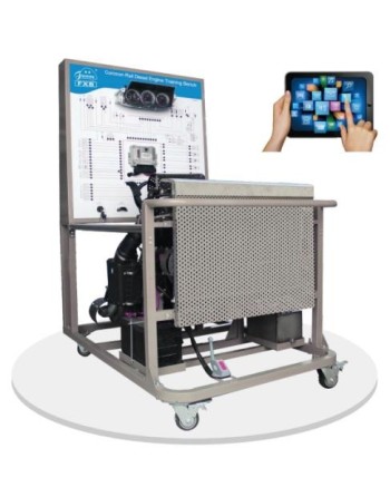
Référence : FXB-A18005 Common Rail Diesel Engine Training Bench
The FXB-A18005 training bench is designed for studying the operation, diagnostics, and maintenance of electronically controlled high-pressure Common Rail diesel engines. Based on an engine from a Great Wall Pickup vehicle, it enables trainees to simulate different engine operating conditions and investigate electronic engine management, fuel injection, and turbocharging systems.
Equipped with measurement terminals, an automotive diagnostic interface, and a wireless fault simulation system, this training bench is suitable for technical schools, vocational training centers, and institutions specializing in automotive maintenance.
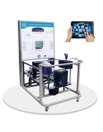
Reference : FXB-B01017 Automated Dry Dual-Clutch Transmission Training Bench
The FXB-B01017 training bench is designed for practical instruction in automated manual transmissions equipped with a dry dual-clutch system. Based on a real, operational automotive transmission, it enables learners to study the mechanical structure, clutch and gear-shifting actuators, and electronic transmission control principles.
Driven by an adjustable-speed three-phase electric motor, the bench supports demonstrations of selector positions, starting in neutral, gear changes, and reverse operation. It also incorporates measurement terminals, a diagnostic interface, display instruments, and an educational fault simulation and assessment system.
This training bench is suitable for vocational training centres, technical education institutions, specialised training institutes, and engineering schools offering courses in automotive mechanics, automated transmissions, onboard electronic systems, and vehicle diagnostics.
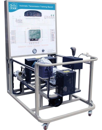
Référence : FXB-B01007 All-Wheel-Drive Automatic Transmission and Differential Training Bench
The FXB-B01007 training bench is designed for practical instruction in the operating principles of all-wheel-drive (AWD) automatic transmission systems. Featuring a cutaway automatic transmission and differential, it enables learners to observe key mechanical components and understand their operation, including the torque converter, planetary gear sets, clutch discs, and gear-shifting mechanisms.
Equipped with an electric motor for dynamic operation, a gear selector lever, and an instructional panel displaying mechanical and hydraulic diagrams, this training bench is suitable for vocational training centres, technical institutes, engineering schools, and automotive training laboratories.
This training bench is intended for practical exercises and demonstrations in automotive mechanics, automatic transmissions, all-wheel-drive systems, and vehicle maintenance. It is suitable for vocational training centres, technical institutes, engineering schools, and specialised automotive technology laboratories.
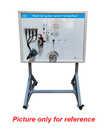
Reference : FXB-A09005 Breaker-Point Ignition System Training Panel
The FXB-A09005 is an educational training panel designed to demonstrate the operation and maintenance of conventional automotive breaker-point ignition systems. Using real, functional components, it enables learners to understand ignition system architecture, perform electrical measurements, study ignition timing and carry out fault-diagnosis exercises.
Designed for technical schools, vocational training centers and automotive training laboratories, this equipment provides a practical learning platform that combines theoretical instruction with hands-on activities. The reference vehicle model is the BJ212.
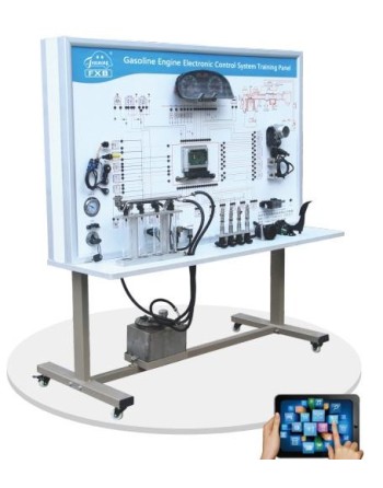
Reference : FXB-A15003 Gasoline Engine Electronic Control System Training Panel
The FXB-A15003 training panel is designed for studying, understanding and diagnosing gasoline engine electronic control systems. Based on actual components from the engine management system of a Volkswagen Jetta 1.6L, it enables trainees to study system architecture, operating principles and the interactions between sensors, actuators and the engine electronic control unit (ECU).
Suitable for technical schools, vocational training centers and automotive training institutions, this training panel supports electrical measurements, component signal analysis and practical fault diagnosis using a compatible automotive diagnostic tool.
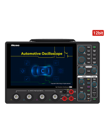

The Micsig AHO1 Series is a professional high-resolution automotive oscilloscope designed for advanced vehicle diagnostics. It features a 12-bit ADC, 200 MHz bandwidth, 4 analog channels, a 1 GSa/s real-time sampling rate, and 110 Mpts memory depth, delivering accurate and reliable measurements for automotive workshops and technical laboratories.
Its ultra-slim 3.1 cm portable design, integrated high-capacity lithium-ion battery, and USB Type-C charging capability make it ideal for mobile diagnostics and on-site maintenance operations.
With its innovative dual software architecture for automotive and general-purpose applications, along with dedicated testing modes for engines, sensors, actuators, and EV systems, the AHO1 Series supports diagnostics for both internal combustion and new energy vehicles.
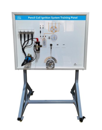
Reference : FXB-A09002 Pencil Coil Ignition System Training Panel
The FXB-A09002 training panel is designed to demonstrate the operation of an automotive pencil-coil ignition system using real components. Suitable for theoretical instruction and practical training, it helps learners study system architecture, analyze electrical signals, examine ignition timing and develop fault-diagnosis skills.
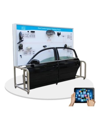
Reference : FXB-I10008 Automotive Door Control System Training Panel
The FXB-I10008 is a didactic training panel designed for studying, demonstrating, and diagnosing automotive door control systems. Based on a Volkswagen vehicle configuration, it incorporates functional components for studying power mirrors, central locking, electric windows, and the anti-theft system. Equipped with electrical test points, LED status indicators, and an intelligent fault simulation system, it is a suitable training solution for technical and vocational education institutions and automotive maintenance training centers.
The FXB-I10008 training panel is particularly suitable for training courses covering:
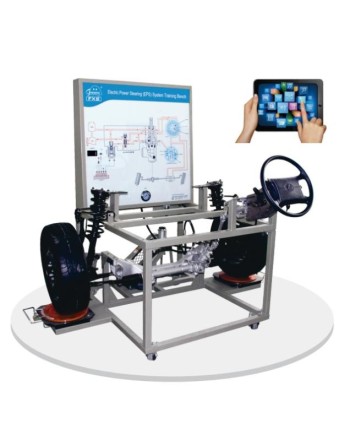
Reference : FXB-F02002 Electric Power Steering (EPS) System Training Bench
This training bench is based on a Volkswagen Magotan-type front axle assembly. It is designed to demonstrate and explain the structure, operation, and control principles of the Electric Power Steering (EPS) system, together with the associated front axle and suspension components.
Designed for technical and vocational schools, specialized educational institutions, and automotive training centers, this equipment provides a practical learning platform for studying electric power steering systems, their electronic components, and their control mechanisms.
The training bench enables users to observe system operation, perform electrical measurements, carry out diagnostic procedures, and practice fault-finding and control-signal analysis.
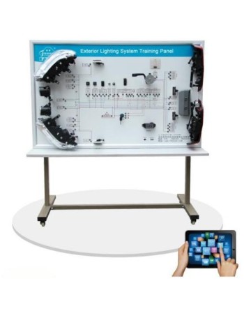
Reference : FXB-I12008 Automotive Lighting and Ignition System Training Panel
The FXB-I12008 is an educational training panel designed for the practical study of automotive exterior lighting and ignition systems, based on the Volkswagen Passat B5 configuration. It enables learners to understand circuit architecture, lighting operation, electrical controls and the main components of the ignition system.
Featuring functional components, electrical measurement terminals and a fault simulation system, this equipment provides a practical training solution for technical schools, vocational training centers and automotive maintenance laboratories.
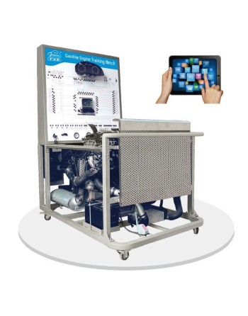
Référence : FXB-A01014 Direct-Injection Gasoline Engine Training Bench
The FXB-A01014 training bench is an educational system designed to study and diagnose electronically controlled direct-injection gasoline engines. Based on the EA211 1.4 T engine, it allows users to simulate different engine operating conditions and analyze the parameters of its control systems.
Designed for technical schools, vocational training centers, and automotive maintenance training institutions, this equipment supports hands-on learning in modern gasoline engine operation, electronic diagnostics, and fault-finding procedures.
The FXB-A01014 training bench is suitable for practical training in the following areas:
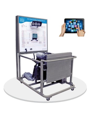
Référence : FXB-A17003 Euro 6 Diesel Engine Training Bench
The FXB-A17003 training bench is designed for practical training in the operation, diagnostics, and maintenance of turbocharged diesel engines incorporating Euro 6 emissions-control technologies. Based on a four-stroke, four-cylinder inline engine with a maximum displacement of 2,000 cc, it enables trainees to study electronic engine management and exhaust after-treatment systems.
Equipped with electrical measurement terminals, an OBD-II diagnostic interface, and an intelligent fault simulation and assessment system, this training bench is suitable for technical schools, specialized institutes, and vocational training centers providing automotive mechanics and diagnostic training.
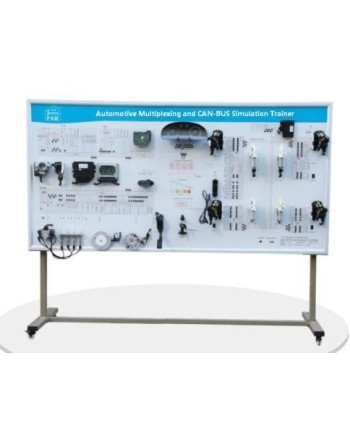
Référence : FXB-XXH055 Banc didactique de multiplexage automobile et de simulation CAN-BUS
The FXB-XXH055 is a training bench designed for studying automotive multiplexing and CAN-BUS communication using functional, genuine automotive components. It enables trainees to examine data exchange between different vehicle electronic systems, including engine management, the instrument cluster, lighting, and diagnostics. Equipped with functional modules, wiring assemblies, and automotive lighting components, it provides a practical training platform for onboard electronics, automotive network architecture, and electrical diagnostics.
The FXB-XXH055 is suitable for vocational training centers, technical institutes, and educational facilities specializing in automotive maintenance and onboard electronics.
It supports practical training in the following areas:
Reference : FXB-A21001 Common Rail Diesel Engine Electronic Control System Training Panel
The FXB-A21001 training panel is designed for learning, studying and diagnosing electronic control systems used in Common Rail diesel engines. Based on a Bosch-type engine management architecture, it incorporates real components to demonstrate the operation of sensors, actuators, the engine control unit (ECU) and the high-pressure fuel injection circuit.
Equipped with measurement terminals, an OBD-II diagnostic interface and an intelligent fault-setting and assessment system, this training panel enables learners to develop practical skills in signal analysis, electronic diagnostics and fault finding. It is suitable for technical schools, vocational training centres and institutions specialising in automotive maintenance.