
- New
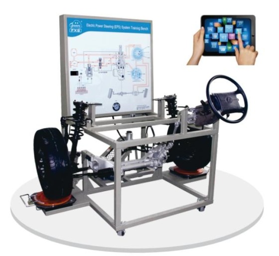
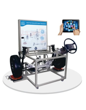

Reference : FXB-F02002 Electric Power Steering (EPS) System Training Bench
This training bench is based on a Volkswagen Magotan-type front axle assembly. It is designed to demonstrate and explain the structure, operation, and control principles of the Electric Power Steering (EPS) system, together with the associated front axle and suspension components.
Designed for technical and vocational schools, specialized educational institutions, and automotive training centers, this equipment provides a practical learning platform for studying electric power steering systems, their electronic components, and their control mechanisms.
The training bench enables users to observe system operation, perform electrical measurements, carry out diagnostic procedures, and practice fault-finding and control-signal analysis.
Electric Power Steering System
Electrical Measurements and Signal Analysis
Electronic Diagnostics
Fault Simulation and Training Assessment
Training Bench Construction
This training bench is suitable for automotive electronics education, electric power steering diagnostics, and maintenance training for electromechanical control systems. It enables trainees to study electrical signals, understand the functions of sensors and control devices, use a compatible diagnostic tool, and develop practical fault-finding and troubleshooting skills.

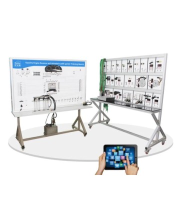
Reference : FXB-A25001 Gasoline Engine Sensors and Actuators Training Bench with Training Panel
This training bench is designed for the study, demonstration, and diagnosis of an automotive gasoline engine electronic management system. Based on original engine sensors and actuators, it enables students to understand the operation of the main components, signal exchanges with the engine electronic control unit (ECU), and the operating principles of fuel injection and ignition control.
The equipment consists of an engine training bench and a training panel. The sensors and actuators are connected to the corresponding terminals on the panel using connection cables, allowing students to study their operation and perform various electrical measurements.
Electronic Engine Management System Study
Integrated Sensors and Actuators
The training bench includes the following components, among others:
Training and Control Panel
The training panel incorporates the main components required for studying the engine management system:
Electrical Measurements and Signal Analysis
Measurement terminals are provided to allow students to observe and analyze the main electrical signals of the system. Practical activities include:
Electronic Diagnostics and Fault Simulation
The training bench is equipped with a diagnostic socket for connecting a compatible automotive diagnostic tool. Depending on the functions supported by the ECU, this interface allows users to:
The wireless fault-setting and educational assessment system allows instructors to introduce faults using a tablet. Students must then identify the anomalies, carry out the required checks, and determine the cause of each fault. This feature supports the assessment of students' knowledge and the development of automotive diagnostic and troubleshooting skills.
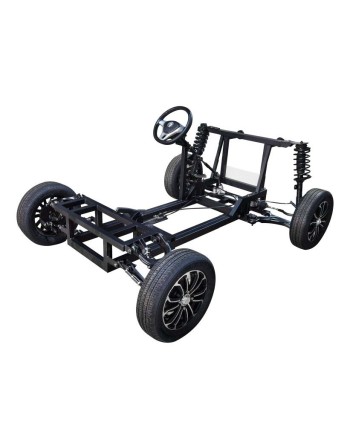
Référence : FXB-G02003 Front and Rear Axle Alignment Training Bench
The FXB-G02003 training bench is designed for studying and practicing front and rear axle geometry inspection and adjustment procedures. Based on the Volkswagen Passat B5, it reproduces the layout of the main suspension and steering components of the actual vehicle, enabling trainees to become familiar with the inspection and adjustment procedures specified by the vehicle manufacturer.
The training bench allows students to study the main angles and parameters involved in wheel alignment.
Front Axle Geometry
Rear Axle Geometry
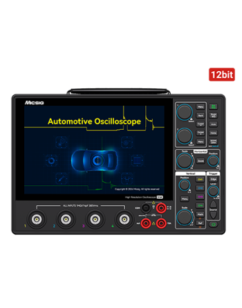

The Micsig AHO1 Series is a professional high-resolution automotive oscilloscope designed for advanced vehicle diagnostics. It features a 12-bit ADC, 200 MHz bandwidth, 4 analog channels, a 1 GSa/s real-time sampling rate, and 110 Mpts memory depth, delivering accurate and reliable measurements for automotive workshops and technical laboratories.
Its ultra-slim 3.1 cm portable design, integrated high-capacity lithium-ion battery, and USB Type-C charging capability make it ideal for mobile diagnostics and on-site maintenance operations.
With its innovative dual software architecture for automotive and general-purpose applications, along with dedicated testing modes for engines, sensors, actuators, and EV systems, the AHO1 Series supports diagnostics for both internal combustion and new energy vehicles.
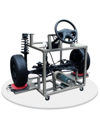
Reference : FXB-F01001 Power Steering and Independent Suspension Training Bench
The Power Steering and Independent Suspension Training Bench is based on the front axle assembly of a Volkswagen Jetta. It is designed to provide a practical demonstration of the structure, operating principles, and functionality of the power steering and front independent suspension systems.
This automotive training equipment is intended for technical and vocational schools, vocational training centers, and institutions specializing in automotive education. It provides a practical teaching platform for theoretical instruction and hands-on training in steering and suspension systems.
The training bench supports component identification, functional demonstrations, operating simulations, and practical assembly and disassembly exercises.
Reference : FXB-F02002 Electric Power Steering (EPS) System Training Bench
This training bench is based on a Volkswagen Magotan-type front axle assembly. It is designed to demonstrate and explain the structure, operation, and control principles of the Electric Power Steering (EPS) system, together with the associated front axle and suspension components.
Designed for technical and vocational schools, specialized educational institutions, and automotive training centers, this equipment provides a practical learning platform for studying electric power steering systems, their electronic components, and their control mechanisms.
The training bench enables users to observe system operation, perform electrical measurements, carry out diagnostic procedures, and practice fault-finding and control-signal analysis.