Home

Home

Active filters

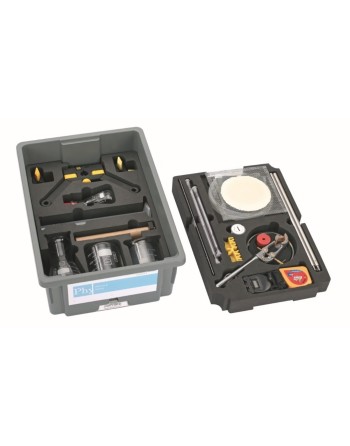
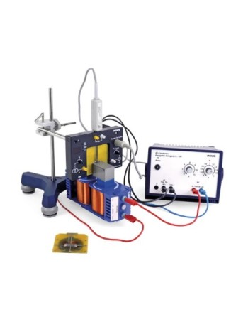
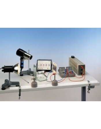
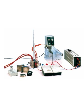
25274-88 - Student TESS Set Heat 1 – Advanced Physics


Logo Phywe


Reference :

25274-88


General Presentation

This educational heat set is designed to investigate the fundamental principles of heat through a complete range of practical experiments. It covers phenomena ranging from the expansion of liquids and gases to boiling point elevation.

Designed for advanced physics education, this set provides a complete solution for conducting educational experiments related to temperature, heat transfer, thermal energy, phase changes, and solutions.


Educational Applications

The set enables 21 student experiments covering the following topics:

  • Thermal equilibrium and temperature measurement
  • Thermal expansion
  • Heat transfer
  • Thermal energy
  • Change of state
  • Solutions

Benefits

  • Complete ready-to-use equipment set
  • Minimal preparation time
  • Easy and fast experiment setup
  • Designed in accordance with educational curricula
  • Comprehensive coverage of key heat-related topics


25271-88 - Student TESS Set, Mechanics 1


Logo Phywe


Reference :

25271-88


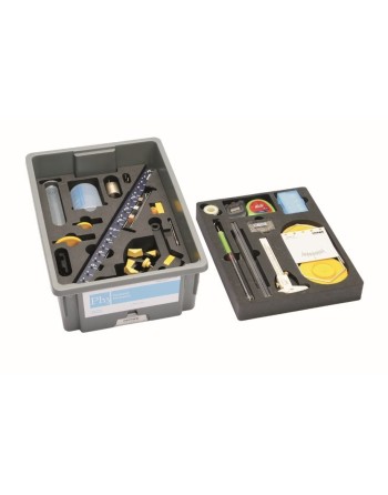
25271-88 - Student Set Mechanics 1, TESS Advanced Physics

Function and Applications

The Student Set Mechanics 1, TESS Advanced Physics is a complete educational kit designed for the study of the fundamental principles of mechanics. It enables a wide range of experiments, from Hooke’s Law to coupled pendulums.

This basic equipment set allows the performance of 32 experiments covering the following topics:

  • Physical quantities and characteristics
  • Forces
  • Elementary machines
  • Liquids and gases
  • Oscillations

Benefits

  • Complete ready-to-use equipment set with minimal preparation time.
  • Digital experiment descriptions available via QR code.
  • Aligned with educational curricula.
  • Modular stand material that is flexible, durable, and stable.
  • Color-coded movable parts to facilitate understanding of mechanical processes.

Equipment and Technical Data

The set is supplied in a sturdy and stackable storage box containing all components required to conduct the experiments.

The storage box includes a precisely fitting foam insert to protect the components and allow quick checking for completeness.


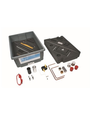
15275-88 - Student TESS Set Heat 2 – Advanced Physics


Logo Phywe


Reference :

15275-88


Function and Applications

The Student Set Heat 2, TESS Advanced Physics is an advanced educational kit designed for the in-depth study of thermal phenomena. It enables a wide range of experiments, from temperature measurement using a thermocouple to the conversion of mechanical energy into internal energy.

This kit is a supplementary equipment set for the Student Set Heat 1 and, when used together, allows 13 additional student experiments in the following areas:

  • Thermal equilibrium and temperature measurement
  • Thermal expansion
  • Heat transfer
  • Thermal energy
  • Change of state
  • Solutions

Benefits

  • Additional thermodynamics experiments covering heat conduction, heat capacity, and energy conversion.
  • Complete equipment set including all required components for minimal preparation time and fast experiment setup.
  • Digital experiment descriptions available through QR codes.
  • Aligned with educational curricula and covering all key thermodynamics topics.

Technical Specifications

  • Supplied in a durable and stackable storage box.
  • Custom-fit foam insert for secure component protection.
  • Quick and easy inventory checking through organized storage.
  • Includes all essential components required to perform the experiments.
  • Equipment must comply with CE standards.


EduKit-PA - Kit for a Processing Station


Festo Logo

References :

  • Basic Version : 549822
  • Advanced Version : 564631 (Add-on)


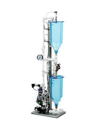
The EduKit-PA Process Automation Kit is a comprehensive educational solution designed to provide structured, hands-on training in process automation, mechatronics, and Industry 4.0 technologies. Its modular architecture supports progressive learning — from fundamental principles to fully software-controlled automation systems.

Key Advantages

  • Structured introduction to mechatronics, automation technology, and core Industry 4.0 concepts
  • Highly modular design enabling scalable learning: from standalone modules to complete workstations and software-controlled learning factories
  • Flexible configuration allowing independent system modifications and project-based expansion
  • Comprehensive instructional materials that break complex topics into manageable learning units
  • Dedicated educational software environment built around a Manufacturing Execution System (MES) developed specifically for teaching
  • Integration of modern learning tools such as QR codes and augmented reality for enhanced interaction and engagement


Hydrogen Generator with Photovoltaic Bench


Logo Heliocentris

References :

  • SHE-811 Solar Hydrogen Extension 30 nl/h
  • SHE-812 Solar Hydrogen Extension 72 nl/h


The Solar Hydrogen Trainer is a 400 Wp off-grid photovoltaic system combined with an electrolyzer for on-site hydrogen production. Using clean solar energy, the system generates hydrogen sustainably and can be integrated with the Fuel Cell Trainer or the Nexa® Training System to form a comprehensive micro-laboratory platform.

The system enables complete energy balancing of the solar hydrogen generation process. Performance and production data from the PV modules, power electronics, battery storage, and electrolyzer are displayed in the included software and can be logged and exported for further analysis. Energy flows between individual components are clearly visualized, providing full system transparency.

Mobile solar modules with adjustable tilt angles and optional solar sensors allow for advanced experimentation in photovoltaic performance and system optimization.


Key Features

  • Fundamentals of solar photovoltaic power generation
  • Operating principles of off-grid solar systems
  • Efficiency analysis of solar hydrogen production
  • System dimensioning of solar hydrogen applications
  • Dedicated focus on Power-to-Gas training concepts

Sample Experiments

  • Optimization of solar module alignment
  • Determination of electrolyzer efficiency
  • Performance analysis and behavior of photovoltaic modules


FM-100B - Fundamental Fluid Mechanics Training Set


Logo ADF Didactic

Reference : FM-100B


General Description

The FM-100B Fundamental Fluid Mechanics Training Set is a base module designed to supply various experimental units in fluid mechanics. It provides a complete educational platform featuring a closed water circuit with a storage tank, submersible pump, and measuring tank.

This system is ideal for engineering laboratories and technical training environments, enabling hands-on experiments and accurate analysis of hydraulic phenomena, including volumetric flow rate measurement and flow behavior.


Compatible Modules

The FM-100B unit supports the following experimental modules:


FM-100.02 - Bernoulli’s Principle


Logo ADF Didactic

Reference : FM-100.02


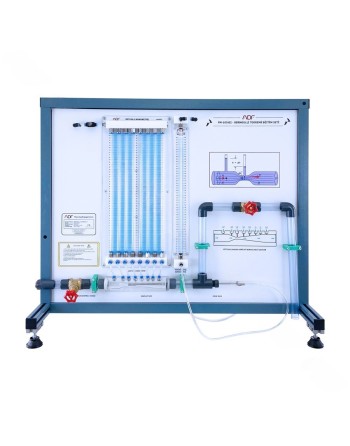
Product Description

The FM-100.02 experimental unit is designed to demonstrate Bernoulli’s principle, which describes the relationship between fluid flow velocity and pressure. According to this principle, an increase in flow velocity results in a decrease in static pressure, while the total pressure remains constant. This is a direct application of the conservation of energy in fluid flow.

This educational unit is ideal for technical training and laboratory environments, enabling clear visualization and accurate measurement of pressure variations within a Venturi nozzle.


Installation and Supply

The experimental unit can be easily and securely positioned on the working surface of the FM-100B base module. Water supply and flow rate measurement are provided directly by this module, ensuring simple, efficient, and reliable operation in laboratory and educational environments.


FM-100.04 - Method of Flow Measurement


Logo ADF Didactic

Reference : FM-100.04


Product Description

Flow rate measurement is a fundamental aspect of measurement technology. The FM-100.04 experimental unit enables students to explore, understand, and apply various flow measurement methods in pipe systems.

Featuring transparent components and integrated measuring instruments, this unit allows direct visualization of internal processes, enhancing practical learning and comprehension of fluid mechanics principles.


Educational Applications

This unit is ideal for:

  • Fluid mechanics laboratory experiments
  • Technical and engineering education
  • Demonstration of flow measurement principles
  • Comparative analysis of measurement devices


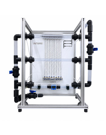
FM-100.03 - Osborne Reynolds Experiment


Logo ADF Didactic

Reference : FM-100.03


General Description

The FM-100.03 - Osborne Reynolds Experiment is a didactic training unit designed to clearly demonstrate the flow characteristics of liquids. It enables the visualization of laminar and turbulent flow regimes through a vertical representation of flow lines.


Educational Benefits

  • Direct visualization of fluid dynamics phenomena
  • Clear understanding of flow regimes
  • Safe and easy operation
  • Ideal for teaching laboratories and technical training centers


Applications

  • Fluid mechanics education
  • Hydraulic engineering laboratory work
  • Academic demonstrations
  • Technical and university training programs


FM-100.07 - Cavitation Module


Logo ADF Didactic

Reference : FM-100.07


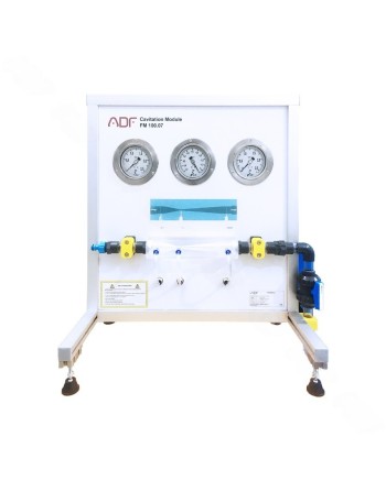
Product Description

The FM-100.07 is an educational unit designed to demonstrate cavitation phenomena in fluid systems. Cavitation occurs when the static pressure drops to the vapor pressure due to increased flow velocity, leading to the formation of vapor bubbles.

These bubbles collapse when pressure rises again, making the process observable and measurable.


Installation and Supply

The experimental unit can be easily and securely positioned on the working surface of the FM-100B base module. Water supply and flow rate measurement are provided directly by this module, ensuring simple, efficient, and reliable operation in laboratory and educational environments.


FM-100.08 - Centrifugal Pump Training Unit


Logo ADF Didactic

Référence : FM-100.08


General Description

The FM-100.08 is an experimental unit designed for the comprehensive study of centrifugal pumps. This turbomachine enables users to understand fluid transport principles and to record typical pump characteristic curves.

The unit includes a self-priming centrifugal pump, a ball valve on the outlet side, and manometers on both inlet and outlet sides. It is powered by an asynchronous motor with continuously adjustable speed via a frequency converter.


Benefits

  • Ideal for education and technical training
  • Clear visualization of pump performance
  • Precise and easy adjustments
  • Robust and safe design


Installation and Supply

The experimental unit can be easily and securely positioned on the working surface of the FM-100B base module. Water supply and flow rate measurement are provided directly by this module, ensuring simple, efficient, and reliable operation in laboratory and educational environments.


FM-100.10 – Measurement of Jet Forces


Logo ADF Didactic

Reference : FM-100.10


General Description

The FM-100.10 is an educational and experimental unit designed to study forces generated by fluid jets. When a flowing fluid is accelerated, decelerated, or deflected, its velocity changes, resulting in a variation of momentum and consequently producing measurable forces.

In practical engineering applications, these forces are used to convert kinetic energy into mechanical work, such as in Pelton turbines.


Operating Principle

The unit generates a water jet directed at interchangeable deflectors. The jet is deflected at different angles, producing forces that can be measured.

The jet force is adjusted by varying the flow rate. Experiments allow investigation of:

  • The influence of flow velocity
  • The effect of flow rate
  • The impact of different deflection angles

Measured forces are compared with theoretical values calculated using the momentum equation.


Scope of Delivery

  • Transparent tank for visual observation
  • Nozzle for jet generation
  • 4 interchangeable deflectors
  • Weight-loaded scale for force measurement
  • Set of calibrated weights


Installation & Compatibility

The unit is designed for easy and secure placement on the FM-100B base module.

Water supply and flow rate measurement are provided by the base module. Alternatively, the unit can be operated using a laboratory water supply.


BSS2000 - Battery Simulation Software


Logo ITECH


References :

BSS2000 Battery Simulation Software

BSS2000 Pro Battery Simulation Software, Pro Version

BSS2000M Battery Simulation Software (multi-channel)


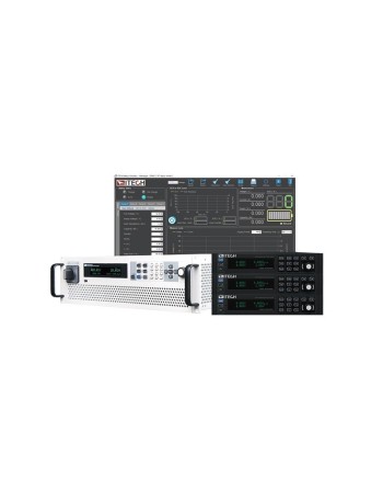
BSS2000 / BSS2000 Pro Battery Simulation Software

The BSS2000 series battery simulation software, including BSS2000, BSS2000 Pro, and BSS2000M multi-channel versions, is designed to work seamlessly with ITECH’s latest high-performance bidirectional DC power supplies, including:

  • IT6000B
  • IT6000C
  • IT6000PV
  • IT-M3600
  • IT-M3400
  • IT2700
  • IT6600C
  • IT6600PV
  • T-M3900B
  • IT-M3900C

Covering power ranges up to 10 MW, the solution provides comprehensive battery simulation capabilities—from low-power battery modules to high-power traction battery systems. The BSS2000 software family is specifically engineered for advanced battery testing applications. It helps reduce the cost and logistical challenges associated with purchasing, storing, and maintaining multiple physical battery types. In addition, the simulator enables rapid configuration of different State of Charge (SoC) levels without performing actual charge/discharge cycles, significantly improving test efficiency and repeatability.


Key Features

  • Battery simulation range up to 2250 V / 10 MW
  • Multi-channel battery module status simulation
  • Bidirectional regenerative battery simulation with efficiency up to 95%
  • Seamless switching between charging and discharging modes
  • Support for user-defined battery characteristic curve import
  • Rapid configuration of battery curves using standard parameter inputs
  • .mat file import support*²
  • Customizable BMS protocol with CAN bus communication to external control units
  • Built-in battery models including:
    • Lead-acid
    • Lithium-ion (Li-ion)
    • LMO
    • NMC (LNMCO)
    • LNMCO & LMO hybrid
    • LFP
    • LTO
    • NiMH*¹
  • Configurable battery protection parameters
  • Adjustable initial State of Charge (SoC) settings
  • Automated data report generation
  • Battery curve preview and real-time curve display
  • Flexible parallel expansion for higher current and power requirements
  • Support for up to 20 battery simulation channels*³

Version Notes

*¹ The BSS2000 basic version supports simulation of lead-acid and lithium-ion batteries.
*² Available in BSS2000 Pro and BSS2000M multi-channel versions.
*³ Available in the BSS2000M multi-channel version.


Process Simulation Panel for Simatic PLC


Hera_carre.jpg

References :

  • 950.062.200 Process Simulation Panel for PLC S7-1500
  • 950.032.800 Process Simulation Panel for PLC S7-1200


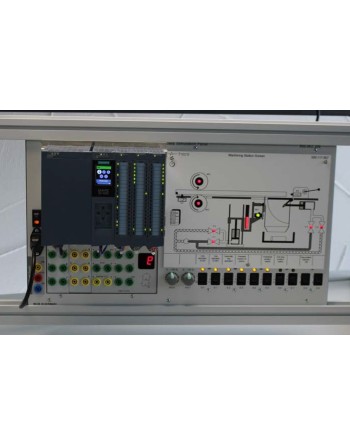
General Description

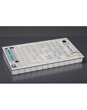
The PLC Process Simulation Panel provides a practical and efficient solution for simulating industrial processes without the need for PC-based software. Output signals are visualized directly through LEDs, running lights, a 7-segment display, and an acoustic buzzer.

This system is ideal for training, testing, and validating PLC programs in both educational and industrial environments.


Included Process Simulations

The panel includes multiple pre-configured process simulations:

  • Star-Delta Connection
  • Staircase Lighting
  • Intruder Alarm System
  • Traffic Lights (traffic-dependent and independent)
  • Conveyor Belt with Buffer Storage
  • Segment Gate Control
  • Machining Station
  • Bottling Plant
  • Mixing Vessel


Compatibility and Integration

The panel is equipped with a DIN rail for mounting Siemens PLCs, including:

  • Siemens S7-1200 (e.g., S7-1215C DC/DC/DC)
  • Siemens S7-1500 (e.g., S7-1512C-1PN)
  • ET200S for decentralized control

It can also be controlled using an external PLC via 4 mm input/output connectors.


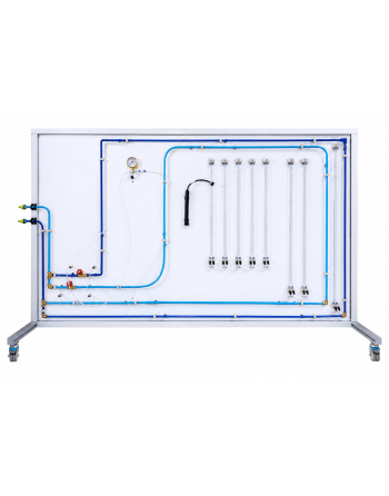
FM-100.12 - Pipe Friction in Laminar and Turbulent Flow


Logo ADF Didactic

Référence : FM-100.12


General Description

The FM-100.12 experimental unit is designed for the detailed study of pressure losses in pipes under both laminar and turbulent flow conditions. During fluid flow through pipes, pressure losses occur due to internal fluid friction as well as friction between the fluid and the pipe wall.

This unit enables the determination of the friction factor, a dimensionless parameter essential for calculating pressure losses. The friction factor is closely related to the Reynolds number, which represents the ratio of inertial forces to viscous forces.

The system allows analysis of the relationship between pressure loss and flow velocity, as well as experimental determination and comparison of friction factors with theoretical values.


Operating Principle

The unit includes a small-diameter pipe section where both laminar and turbulent flows can be generated. The Reynolds number and friction factor are determined based on measured flow rate and pressure losses.

In turbulent flow conditions, the pipe is directly supplied from the water network. For laminar flow, a constant pressure is maintained using a standpipe with overflow. Flow rate is controlled using valves.


Experiments

  • Measurement of pressure losses in laminar flow
  • Measurement of pressure losses in turbulent flow
  • Determination of critical Reynolds number
  • Determination of pipe friction factor
  • Comparison of experimental and theoretical friction factors


Tektronix High-Voltage Differential Probes


Logo Tektronix

References :

  • TMDP0200 25x/250x, 750 V, 200 MHz, TekVPI
  • THDP0200 50x/500x, 1'500 V, 200 MHz, TekVPI
  • THDP0100 100x/1000x, 6'000 V, 100 MHz, TekVPI
  • P5200A 50x/500x, 1'300 V, 50 MHz, BNC
  • P5202A 20x/200x, 640 V, 100 MHz, TekProbe
  • P5205A 50x/500x, 1'300 V, 100 MHz, TekProbe
  • P5210A 100x/1000x, 5'600 V, 50 MHz, TekProbe


General Description

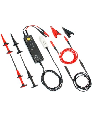
High-voltage differential probes provide a professional and safe solution for measuring high-voltage electrical signals in demanding environments. They are designed to deliver accuracy, reliability, and safety while enabling differential measurements on floating circuits using ground-referenced oscilloscopes.


Key Technical Specifications

Performance

  • Bandwidth: up to 200 MHz
  • Maximum differential voltage: up to 6'000 V (DC + peak AC)
  • Common mode voltage: up to 2'300 V RMS

Key Features

  • Overrange indicator
  • Safety certified
  • Switchable attenuation
  • Switchable bandwidth limit


Applications

  • Floating measurements
  • Switching power supply design
  • Motor drive design
  • Electronic ballast design
  • CRT display design
  • Power converter design and service
  • Power device evaluation

GCP-300/500 /1000 - Current Probes


Logo GW Instek


Références

  • GCP-300 : Current probe, 400 A, DC à 300 kHz
  • GCP-500 : Current probe, 200 A, DC à 500 kHz
  • GCP-1000 : Current probe, 70 A, DC à 1 MHz


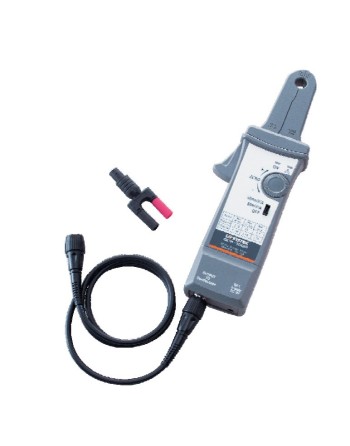
The GCP-300, GCP-500, and GCP-1000 current probes are high-precision instruments designed for accurate AC and DC current measurements. With wide bandwidth and versatile measurement ranges, they are ideal for industrial, electronic, and laboratory applications.


Key Features

Bandwidth
  • GCP-300: DC to 300 kHz
  • GCP-500: DC to 500 kHz
  • GCP-1000: DC to 1 MHz
Maximum Measurement Range
  • GCP-300: 400 A (10 mV/A) and 40 A (100 mV/A)
  • GCP-500: 200 A (20 mV/A) and 20 A (200 mV/A)
  • GCP-1000: 70 A (500 mV/A) and 7 A (50 mV/A)
Additional Features
  • Overload indicator
  • AC and DC current measurement capability
  • High accuracy across wide frequency ranges


Applications

  • Harmonic current measurement
  • Inrush current analysis
  • Current ripple and noise measurement


FluidSIM® - Simulation Sofware


Festo Logo


Floating Licenses

  • 8198189 – FluidSIM Pneumatics, Floating License
  • 8198190 – FluidSIM Hydraulics, Floating License
  • 8198191 – FluidSIM Electrical Engineering, Floating License


Learning Objectives

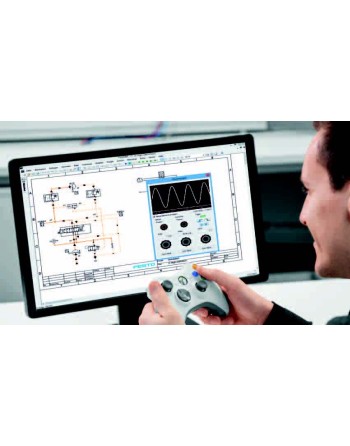
  • Design and develop circuit diagrams
  • Identify and prevent design errors
  • Simulate and optimize circuit solutions
  • Understand structured solution development in automation engineering
  • Analyze the impact of technical modifications within a system architecture through real-time simulation


Key Benefits

  • High-definition interactive simulation
  • Integration of virtual and real measuring instruments
  • Extensive component library
  • Intuitive user interface
  • Comprehensive teaching materials included


AFG-2100 / AFG-2000 Series - Arbitrary Function Generator 5 /12 /25 MHz


Logo GW Instek


References

  • AFG-2005 : Arbitrary Function Generator, 0,1 Hz à 5 MHz
  • AFG-2105 : Arbitrary Function Generator, 0,1 Hz à 5 MHz, with modulation, sweep, and counter
  • AFG-2012 : Arbitrary Function Generator, 0,1 Hz à 12 MHz
  • AFG-2112 : Arbitrary Function Generator, 0,1 Hz à 12 MHz, with modulation, sweep, and counter
  • AFG-2025 : Arbitrary Function Generator, 0,1 Hz à 25 MHz
  • AFG-2125 : Arbitrary Function Generator, 0,1 Hz à 25 MHz, with modulation, sweep, and counter


Overview

The AFG-2100 / AFG-2000 Series is a range of DDS (Direct Digital Synthesis) based arbitrary function generators designed to meet the needs of educational and industrial environments. It provides a precise, stable, and cost-effective signal source capable of generating sine, square, triangle, noise, and arbitrary waveforms.

With a frequency range from 0.1 Hz up to 5 / 12 / 25 MHz, 0.1 Hz resolution, 20 MSa/s sampling rate, 10-bit vertical resolution, and 4k-point waveform memory, the series offers high flexibility for custom waveform generation.


Key Features

  • Frequency range: 0.1 Hz to 5 / 12 / 25 MHz
  • Frequency resolution: 0.1 Hz
  • Waveforms: Sine, Square, Triangle, Noise, Arbitrary
  • Sampling rate: 20 MSa/s
  • Vertical resolution: 10-bit
  • Waveform memory: 4k points
  • Adjustable duty cycle: 1% to 99% (square wave)
  • Adjustable symmetry: 0% to 100% (ramp)
  • 3.5-inch LCD display
  • USB interface for remote control
  • PC waveform editing software


Advanced Features (AFG-2100 Series Only)

  • AM / FM / FSK modulation
  • Sweep function
  • Built-in frequency counter up to 150 MHz


Applications

  • Education and training
  • Analog and digital circuit testing
  • Signal simulation and prototyping
  • Audio and RF testing
  • Automated test systems (ATE)


SFG-1000 Series - 3 MHz Function Generator


Logo GW Instek


References

  • SFG-1003 : Function Generator, 0,1 Hz to 3 MHz
  • SFG-1013 : Function Generator, 0,1 Hz to 3 MHz, dual display


Overview

This DDS (Direct Digital Synthesis) based function generator provides a reliable, accurate, and cost-effective solution for signal generation in educational, laboratory, and industrial environments. Built on an advanced FPGA architecture, it ensures high stability and precision while maintaining ease of use.

With a frequency range from 0.1 Hz to 3 MHz and fine resolution, this device is ideal for applications requiring accurate signal generation without unnecessary complexity.


Key Features

  • DDS technology with FPGA design
  • Frequency range: 0.1 Hz to 3 MHz
  • Frequency resolution: 100 mHz
  • Frequency accuracy: ± 20 ppm
  • Frequency stability: ± 20 ppm
  • Low distortion: -55 dBc (0.1 Hz to 200 kHz)
  • Voltage display (SFG-1013)
  • Multiple outputs: analog and TTL


Waveform Types

  • Sine
  • Square
  • Triangle
  • TTL output


Applications

  • Automatic control training
  • Vibration testing
  • Electronic device testing and adjustment
  • Circuit validation and troubleshooting
  • Laboratory experiments


Key Advantages

  • High signal stability and accuracy
  • Low distortion for reliable measurements
  • User-friendly interface
  • Cost-effective solution
  • Versatile for educational and technical use


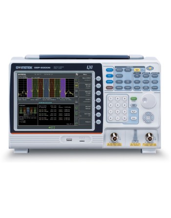
GSP-9330 - Spectrum Analyzer 9 kHz to 3,25 GHz


Logo GW Instek


Référence

  • GSP-9330 : Spectrum Analyzer 9 kHz to 3,25 GHz


Key Features

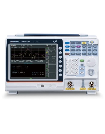
  • Frequency range: 9 kHz to 3.25 GHz
  • High frequency stability of 0.025 ppm with 1 ppm aging rate
  • Resolution bandwidth (RBW): 1 Hz to 1 MHz (3 dB)
  • 6 dB EMI filters: 200 Hz, 9 kHz, 120 kHz, 1 MHz
  • Ultra-fast sweep time: up to 204 µs
  • Sensitivity: –149 dBm/Hz (with preamplifier enabled)
  • Integrated preamplifier and 50 dB attenuator
  • Sequence function for automated test routines
  • Built-in EMC pre-compliance function with Quasi-Peak and Average EMI detection modes
  • Integrated 2FSK analysis and AM/FM/ASK/FSK demodulation and analysis
  • Advanced measurement capabilities including:
    P1dB, Harmonics, Channel Power (CHPW), Occupied Channel Bandwidth (OCBW),
    Adjacent Channel Power Ratio (ACPR), Spectrum Emission Mask (SEM),
    Third-Order Intercept (TOI), Carrier-to-Noise Ratio (CNR),
    Composite Triple Beat (CTB), Composite Second Order (CSO),
    N-dB bandwidth, Noise Marker, Frequency Counter,
    Time Domain Power (TDP), and Gated Sweep
  • Multiple display modes: Spectrogram, Topographic, and Split-Window
  • Remote EMI measurement software: SpectrumShot
  • Remote control interfaces: LAN, USB, RS-232
  • Optional accessories: Tracking Generator, GPIB interface


Applications

  • Rapid verification and analysis of spectral characteristics
  • EMI pre-compliance testing
  • Analysis of ASK, FSK, AM, and FM signal characteristics
  • Monitoring of satellite uplink signals from mobile uplink vehicles
  • Ideal for systems requiring a compact and high-performance instrument
  • Measurement of frequency response for cables, attenuators, filters, and amplifiers


GSP-9300B - Spectrum Analyzer 9 kHz to 3 GHz


Logo GW Instek


Reference

  • GSP-9300B : Spectrum Analyzer 9 kHz to 3 GHz


The GSP-9300B Spectrum Analyzer delivers high-precision measurement performance and advanced analysis capabilities, making it an ideal solution for RF testing, signal analysis, research laboratories, and production environments.

Key Features

  • Frequency Range: 9 kHz to 3 GHz
  • Frequency Stability: 0.025 ppm with 1 ppm annual aging rate
  • Integrated Hardware: Built-in preamplifier, 50 dB attenuator, and sequence function
  • Resolution Bandwidth (RBW): 1 Hz to 1 MHz
  • Sensitivity: –149 dBm/Hz (with preamplifier enabled)
  • Demodulation & Analysis: Integrated AM/FM demodulation and analysis functions
  • Comprehensive Measurement Functions:
    P1dB point, harmonic analysis, channel power, N-dB bandwidth, occupied bandwidth (OCBW), adjacent channel power ratio (ACPR), spectrum emission mask (SEM), third-order intercept (TOI), carrier-to-noise ratio (CNR), composite triple beat (CTB), composite second order (CSO), noise marker, frequency counter, time-domain power, and gated sweep
  • Display Modes: Spectrogram, topographic view, and dual-view display
  • Remote Control Interfaces: LAN, USB, and RS-232
  • Optional Accessories: Tracking generator and GPIB interface

The GSP-9300B combines precision, versatility, and ease of integration to meet the demanding requirements of modern RF applications.


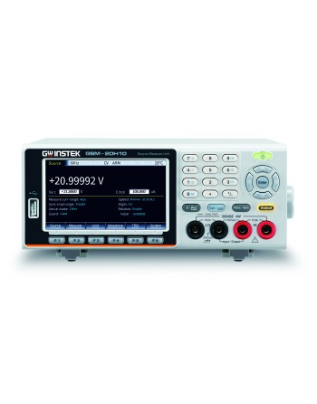
GSM-20H10 – Precision Source Measure Unit (SMU)


Logo GW Instek


Reference

  • GSM-20H10 : Precision Source Measure Unit (SMU)


Key Features

  • Maximum output: ±210 V / ±1.05 A / 22 W
  • 4 built-in sequence output modes with up to 2500 points
  • OVP (Over Voltage Protection) and OTP (Over Temperature Protection)
  • 0.012% basic measurement accuracy with 6½-digit resolution
  • Variable sampling speed
  • SDM (Source Delay Measure) cycle
  • 2-wire, 4-wire, and 6-wire remote voltage source and measurement sensing
  • Adjustable display digits
  • Built-in limit function
  • 5 built-in calculation functions
  • Standard SCPI command support
  • Interfaces: RS-232, USBTMC, LAN, GPIB (optional)
  • 4.3" TFT LCD display with numeric keypad
  • Built-in RTC clock


Training Module: Basics to Operational Amplifiers


Hera_carre.jpg


Reference :

  • 510.100.530 – Module amplificateur opérationnel


Overview

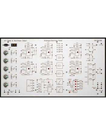
The Operational Amplifier Panel is a compact and comprehensive training system designed to provide in-depth knowledge of operational amplifier (op-amp) circuits. It is ideally suited for learning, designing, and troubleshooting electronic laboratory devices.

The panel is equipped with 11 μA741 operational amplifiers and 5 potentiometers for precise voltage adjustment, making it an efficient educational tool for technical training environments and laboratories.


Learning Content

  • Differential amplifier
  • Inverting and non-inverting circuits
  • Impedance converter
  • Calculation circuits (summing, subtraction, multiplication)
  • Comparator circuits (threshold switch, Schmitt trigger)
  • Constant current and constant voltage sources
  • Precision voltage source and precision rectifier circuits
  • Astable and monostable multivibrators
  • Integrator
  • Function generator (triangle, sawtooth)
  • Differentiator
  • RC oscillator with op-amp
  • AC voltage amplifier
  • Squaring and root extraction using diode networks
  • A/D and D/A converters with R-2R networks
  • Divider and root extraction


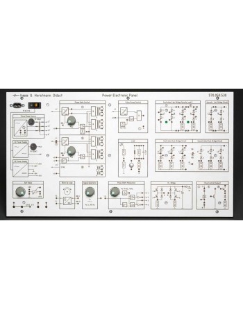
Training Module: Basics of Power Electronics


Hera_carre.jpg


Reference :

  • 570.050.530 – Power Electronics Panel


Overview

The Power Electronics Panel is a compact training system designed for performing experiments in power electronics on DC, single-phase AC, and three-phase AC circuits using a safe low-voltage approach.

The panel includes integrated resistive, inductive, and capacitive loads, enabling a comprehensive understanding of power electronics behavior and applications.

An optional motor/generator module can be added to extend the system capabilities to electromechanical and control system applications.


Single-phase AC Experiments

  • Uncontrolled half-wave rectifier
  • Uncontrolled bridge rectifier
  • Half-controlled bridge rectifier
  • Fully controlled bridge rectifier
  • Line-commutated rectifier
  • Pulse group control


Three-phase AC Experiments

  • Uncontrolled rectifier M3
  • Uncontrolled rectifier B6
  • Controlled rectifier M3
  • Controlled rectifier B6


DC Experiments

  • Basic PWM circuits
  • PWM with H-bridge (MOSFET)


GTO Experiments

  • Trigger pulse manipulation
  • GTO used as chopper


Los Angeles Abrasion and Fragmentation Testing Machine for Aggregates


Noustest Testing Equipement


Reference :

  • NT-A0060 Los Angeles Abrasion and Fragmentation Testing Machine for Aggregates


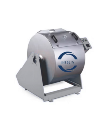
The Los Angeles abrasion machine is a fundamental device used to evaluate the resistance of aggregates to wear and fragmentation. It is designed to comply with major international standards for material durability testing.

The unit can be easily configured to meet ASTM and EN standards, with adjustable settings for the required number of rotations.

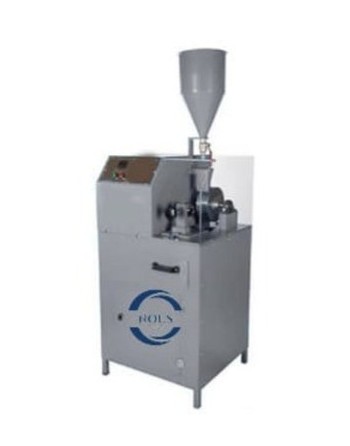
The device consists of a cylindrical steel drum with an inner diameter of 711 mm and an internal length of 508 mm, coupled with an electronic control unit. The drum operates at a speed of 31–33 rpm. The equipment features an automatic counter that stops the machine once the preset number of cycles has been completed. A collection tray is included for easy sample removal.

In accordance with EN standards, the abrasive ball set and the 1.6 mm sieve must be ordered separately. For AASHTO and ASTM standards, the abrasive ball set and the 1.7 mm mesh sieve must also be ordered separately.


NT-A0230 – Micro-Deval Test Apparatus


Noustest Testing Equipement


Reference :

  • NT-A0230 Micro-Deval Test Apparatus


General description

The NT-A0230 Micro-Deval Test Apparatus is a laboratory testing device designed to determine the resistance to wear of aggregates sized between 25 and 50 mm. The test is performed in accordance with international standards to assess the durability of materials used in applications such as road construction and railway ballast.


Principle and operation

The apparatus simulates aggregate wear by abrasion in a wet environment inside rotating drums. It can operate with:

  • 4 drums of Ø200 × 154 mm
  • or 2 drums of Ø200 × 400 mm

The rotation speed is set to 100 ± 5 rpm. The unit is equipped with a user-adjustable digital revolution counter and automatically stops at the end of the test cycle.


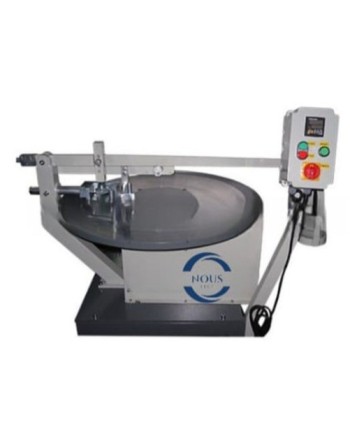
NT-A5160 – Böhme Abrasion Testing Machine


Noustest Testing Equipement


Reference :

  • NT-A5160 Böhme Abrasion Testing Machine


Product Description

The NT-A5160 Böhme Abrasion Testing Machine is designed to determine the abrasion resistance of concrete products and natural stones used for both indoor and outdoor paving applications.


Operating Principle

The machine is equipped with an abrasive grinding wheel of approximately 750 mm diameter, a removable 30 kg test weight, and a clamping device to securely hold the specimen during testing.


NT-A0160 – Vertical Abrasion Tester for Natural Stones and Concrete Tiles


Noustest Testing Equipement


Reference :

  • NT-A0160 Vertical Abrasion Tester for Natural Stones and Concrete Tiles


General Description

The Vertical Abrasion Tester is designed to determine the resistance to wear and abrasion of natural stones, concrete tiles, and paving products used in indoor and outdoor applications. The test simulates real-life wear conditions by subjecting the specimen to rotating abrasive forces under controlled pressure.


LabVolt Series 3535 - Three-Phase Separation System


Festo Logo


Reference : 8094287


Overview

The Series 3535 Three-Phase Separation System is a comprehensive training solution designed for hands-on learning of industrial separation processes. Compact, mobile, and built with real industrial-grade components, it provides an immersive experience aligned with practices used in the energy and process industries.


Key Features

  • Mobile and space-efficient system ideal for laboratory environments
  • Designed with authentic industrial components
  • Two configurations available: Basic Control System and Instrumentation Add-On
  • Integrated smart instrumentation
  • Fault insertion capability for troubleshooting training
  • Operation in both automatic and manual modes


Learning Objectives

1. Basic Control System

  • Understand three-phase separation mechanisms and separator vessel design
  • Analyze the effect of various parameters on separation efficiency
  • Adjust pneumatic level controllers
  • Configure and operate instrumentation specific to three-phase separators
  • Read and interpret Piping and Instrumentation Diagrams (P&ID)
  • Develop troubleshooting and diagnostic skills

2. Instrumentation Add-On

  • Use a Human-Machine Interface (HMI) and efficiently manage alarms
  • Gain practical knowledge of Programmable Logic Controllers (PLCs)
  • Install and operate various types of smart instrumentation
  • Learn the HART communication protocol (optional)


Benefits

  • Ideal for training operators, instrumentation technicians, and engineers
  • Develop industry-relevant skills for operation, troubleshooting, and maintenance
  • Work with equipment commonly used in the oil and gas industry
  • Comprehensive and structured learning resources
  • Enhanced safety with an industrial pressure relief valve and rupture disc


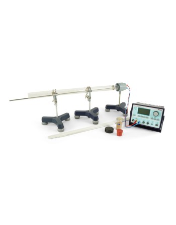
P2210101 - Measuring the Velocity of Light


Logo Phywe


Reference :

P2210101


Function and Applications

This complete system enables the measurement of the velocity of light in air, as well as in transparent media such as liquids and solids. It is ideally suited for laboratory experiments, demonstrations, and educational purposes in optics.


Principle of Operation

The light intensity is modulated, and the phase relationship between the transmitted and received signals is analyzed. The velocity of light is calculated based on the relationship between phase variation and the optical path length.


Benefits

  • Measure the speed of light yourself
  • Analyze how light velocity varies across different materials
  • Compact setup suitable for tabletop use
  • Combined light speed and distance measurement in one device
  • Advanced digital measurement technology for high accuracy
  • Simple design with minimal adjustment requirements
  • Up to 2% accuracy using phase comparison of a high-frequency modulated laser
  • Can be used with or without an oscilloscope
  • Integrated display of all relevant parameters (ƒ, Δφ, Δt, Δx)


Experimental Tasks

  • Determine the velocity of light in air
  • Measure the velocity of light in water and synthetic resin
  • Calculate the refractive indices of different media


Learning Objectives

  • Refractive index
  • Wavelength
  • Frequency
  • Phase
  • Modulation
  • Electric field constant
  • Magnetic field constant


Educational Module – Fundamentals of Digital Technology


Hera_carre.jpg


Reference :

  • 520.010.530 – Module "Fundamentals of Digital"


Overview

The digital panel is designed to provide a comprehensive understanding of commonly used integrated circuits and their implementation using logic gates such as NAND, NOR, XOR, and XNOR.

It is ideally suited for developing practical skills in digital electronics, non-contact control systems, and microcomputer technology.


Learning Content

  • Boolean algebra and Karnaugh diagrams
  • NAND and NOR technologies
  • XOR and XNOR gates (equivalence / anti-equivalence)
  • TTL 74 series (pull-up / pull-down resistors)
  • Schmitt trigger (inverting / non-inverting)
  • SR flip-flops using NAND/NOR gates
  • SR, D, and JK flip-flops
  • Monostable circuits
  • Code converters (8421 BCD to Excess-3, decimal, 7-segment)
  • Arithmetic circuits and carry handling
  • Arithmetic Logic Unit (ALU 74HC/HCT181)
  • Counters (up, down, modulo-n, PLC applications)
  • Registers and shift registers
  • Multiplexers and demultiplexers
  • AD/DA converters


Collaborative Robot Universal Training Platform with DOBOT Magician E6


Logo Dobot


Référence : E6 Training Station


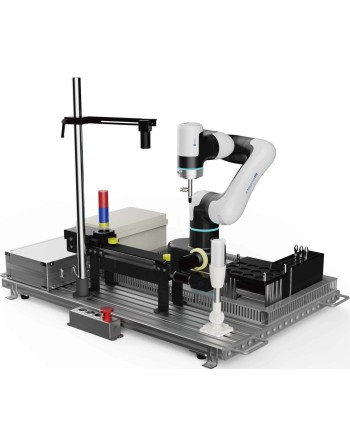
The Collaborative Robot Universal Training Platform is a comprehensive teaching solution designed for vocational education and industrial training centers. It integrates a collaborative robot, control system, vision system, conveyor belt, and various modular components.

With its modular design, the platform offers high flexibility and enables easy simulation of automation scenarios such as object detection, picking, handling, palletizing, and assembly. It also supports educational projects including robot calibration, trajectory tracking, and industrial communication.

This solution helps learners acquire essential skills in smart robotics while enhancing their practical and innovative capabilities.


Key Features

Comprehensive Functionality

The platform supports teaching of robotic calibration, trajectory tracking, communication, and more. Combined with workpiece models, it enables tasks such as object tracking, picking, inspection, transportation, palletizing, and assembly.

Ease of Use

By integrating lightweight collaborative robots (compatible with CR3, E6, and MG400) and flexible modular units, users can easily create automation applications.

High Versatility

The system covers robotics, machine vision, and optional PLC systems. After training, users can handle most automation tasks. The conveyor belt kit can also operate independently.


MHO1 Series – High-Resolution Oscilloscope


Logo Micsig Technologies


References

  • MH14-100 : High-Resolution Oscilloscope 100 MHz, 4 channels, with digital multimeter
  • MH14-200 : High-Resolution Oscilloscope 200 MHz, 4 channels, with digital multimeter
  • MH14-100N : High-Resolution Oscilloscope 100 MHz, 4 channels
  • MH14-200N : High-Resolution Oscilloscope 200 MHz, 4 channels


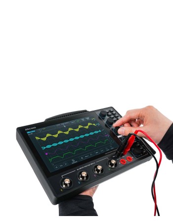
The Micsig MHO1 Series is an ultra-portable, professional-grade high-resolution oscilloscope designed for industrial and educational applications. It features a 12-bit high-precision ADC, bandwidth up to 200 MHz, 4 analog channels, a real-time sampling rate of 1 GSa/s, and memory depth up to 110 Mpts.

With a slim 3.1 cm design, it is highly portable and ideal for field use. The 8-inch capacitive touchscreen (1280 × 800) ensures excellent visibility and a smooth user experience.


Key Features

  • 12-bit vertical resolution (4096 levels)
  • Bandwidth: 100 MHz or 200 MHz
  • DC gain accuracy ≤ 1%
  • Up to 110 Mpts memory depth
  • Advanced math and FFT functions
  • Segmented acquisition mode
  • 8” TFT LCD touchscreen – 1280 × 800
  • High-capacity battery with power bank support
  • Remote control via PC, smartphone, SCPI
  • Built-in serial bus decoding


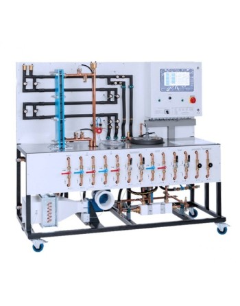
TE-130 – Liquid Heating Engineering Training System


Logo ADF Didactic

Reference : TE-130 - Liquid Heating Engineering Training System


The TE-130 training system is designed for the study of heat transfer processes in liquids for university laboratories, engineering education, and technical training centers. The equipment enables students and researchers to perform practical experiments related to thermal and fluid dynamics processes using real-time measurements and data analysis.


Educational Applications and Laboratory Experiments

The system allows the following laboratory studies and practical experiments:

  • Determination of the heat capacity of a liquid by heating a flowing liquid stream.
  • Determination of liquid viscosity at different temperatures according to laminar flow theory.
  • Determination of the heat transfer coefficient during fluid flow inside a pipe.
  • Analysis of the transferred thermal power in a “pipe-in-pipe” heat exchanger according to different heat carrier flow arrangements.
  • Determination of the transferred thermal power of a shell-and-tube heat exchanger.
  • Study of the characteristics of an air-to-water or air-to-air heat exchanger.


Technical Specifications

  • Robust metal structure with aluminum frame.
  • Integrated electric water heater.
  • Plate heat exchanger.
  • “Pipe-in-pipe” heat exchanger.
  • Air-to-water or air heat exchanger.
  • Circulation pumps.
  • Water tanks.
  • Integrated sensors and flow meters.
  • Connecting pipes, hoses, and valves.
  • Specialized software for data acquisition and processing on a laptop computer.
  • Software interface available in English and/or Russian.
  • All markings, nameplates, and equipment labels are provided in English and/or other langage 


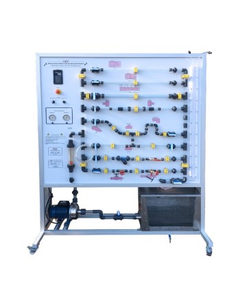
FM-230 – Flow Through Pipes and Fittings Training System


Logo ADF Didactic

Reference : FM-230- Flow Through Pipes and Fittings Training System


The FM-230 training system is designed for the experimental study of head losses in pipes and hydraulic fittings. This educational unit enables students and technicians to analyze fluid behavior in different piping systems, evaluate pressure losses, and study the hydraulic characteristics of valves and pipe components.

The equipment is particularly suitable for fluid mechanics laboratories, applied hydraulics, process engineering education, and technical training centers.


Main Features

  • Study of pressure losses in piping systems.
  • Pressure measurement without interaction through annular chambers.
  • Transparent measuring elements for flow visualization and flow rate determination.
  • Smooth pipes with different diameters.
  • Rough pipe with known roughness for surface effect studies.
  • Variable flow rates for different experimental conditions.


Educational Objectives and Experiments

  • Investigation of head losses in pipes, pipe elements, and hydraulic fittings.
  • Analysis of the effect of flow velocity on pressure losses.
  • Determination of resistance and loss coefficients.
  • Study of the opening characteristics of angle seat valves and gate valves.
  • Familiarization with different flow measurement devices.
  • Study of Venturi nozzle operation.
  • Study of an orifice plate flow meter or measuring nozzle.


FM-100.25 - Energy Losses in Bends and Pipe Fittings


Logo ADF Didactic

Reference : FM-100.25 - Energy Losses in Bends and Pipe Fittings Module


The FM-100.25 module is designed for the experimental study of pressure losses in various pipe fittings and hydraulic components. This educational system enables the analysis of the effects of direction changes, section variations, and control elements on pressure losses within hydraulic circuits.

The unit allows accurate visualization and measurement of pressure losses in several configurations, including sudden contractions, sudden enlargements, pipe bends, pipe angles, and ball valves.


Educational Applications

  • Study of local pressure losses in hydraulic systems
  • Analysis of the influence of pipe fittings on fluid flow
  • Measurement of pressure variations across hydraulic elements
  • Practical training in fluid mechanics and hydraulics
  • Laboratory experiments for engineering schools, technical institutes, and vocational training centers


Main Features

  • Investigation of pressure losses in various pipe fittings and a ball valve
  • Measurement elements include:
    • Sudden contraction
    • Sudden enlargement
    • Pipe bend
    • Segment bend
    • Pipe angle
    • Ball valve
  • Annular chambers for precise pressure measurement
  • 6 tube manometers for differential pressure display
  • Bourdon tube pressure gauge for pressure measurement
  • Flow rate measurement provided through the FM 100 base module
  • Water supply via FM-100B base module or laboratory water supply


Installation and Supply

The experimental unit can be easily and securely positioned on the working surface of the FM-100B base module. Water supply and flow rate measurement are provided directly by this module, ensuring simple, efficient, and reliable operation in laboratory and educational environments.


FM-100.25C – Pressure Losses in Piping Systems


Logo ADF Didactic

Reference : FM-100.25C - Pressure Losses in Piping Systems


The FM-100.25C module is designed for the analysis and investigation of pressure losses in piping systems and hydraulic components. It enables the visualization and measurement of pressure variations generated by different pipe elements, making it an ideal educational solution for fluid mechanics, hydraulics, and process engineering laboratories.


Educational and Experimental Applications

The system allows the study of pressure losses caused by various piping components and flow control elements, including:

  • Sudden contraction
  • Sudden enlargement
  • Standard pipe bend
  • Segment bend
  • 90° pipe angle
  • Ball valve

Integrated annular chambers ensure accurate static pressure measurements at different points of the hydraulic circuit.


Main Features

  • Investigation of pressure losses in pipes and hydraulic fittings
  • Visualization of pressure variations across different piping elements
  • Accurate pressure measurement using annular chambers
  • 6 tube manometers for differential pressure display
  • Bourdon tube pressure gauge for pressure measurement
  • Flow rate measurement via the FM-100B base module
  • Water supply through the FM-100B module or laboratory water supply


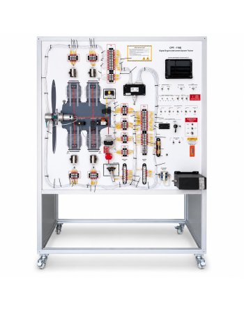
CPT-110E – Digital Engine Instrumentation System Trainer


Logo ADF Didactic

Reference : CPT-110E - Digital Engine Instrumentation System Trainer


The CPT-110E is a complete and fully operational training system designed for the study of aircraft piston engine instrumentation systems. Developed for technical and educational environments, this trainer enables students and trainees to acquire practical skills in aircraft engine instrumentation, maintenance, troubleshooting, and system analysis.
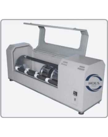
The system reproduces the operation of real aircraft engine sensors and instruments and provides hands-on training for instrument connection, removal, replacement, monitoring, and fault diagnosis procedures.


Training Applications

The trainer is suitable for aviation training centers, engineering schools, technical institutes, and laboratories specializing in aircraft maintenance and avionics systems.

Example ATA Chapters Covered

  • ATA 31-10-00: Instrument and Control Panels
  • ATA 31-20-00: Independent Instruments
  • ATA 31-26-41: Aural Warning Module Removal & Replacement
  • ATA 31-62-12: EFIS Control Panel Removal & Replacement


Main Features

  • Combination of aircraft instrumentation systems and engine instrumentation systems
  • Functional engine monitoring system connected to real or simulated engine sensors
  • Electronic simulation of engine sensors
  • Instructor panel with fault insertion capability
  • Training video support for instructors and teachers
  • Hands-on maintenance and troubleshooting training


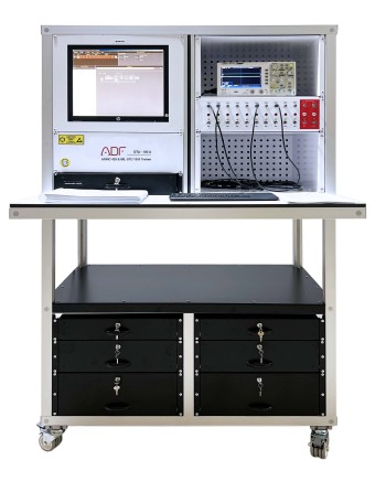
DTA-100 – ARINC 429 & MIL-STD-1553 Training System


Logo ADF Didactic

Reference : DTA-100 - ARINC 429 & MIL-STD-1553 Training System


The DTA-100 training system is an advanced educational platform designed for the study of aircraft data communication systems. It enables trainees to understand, analyze, test, and maintain avionics data bus communication used in modern aerospace applications.

This comprehensive training solution integrates two widely used aviation communication protocols: ARINC 429 and MIL-STD-1553. It provides a complete environment for simulation, troubleshooting, diagnostics, and maintenance of avionics communication networks.


ARINC 429 System

ARINC 429 is a digital communication standard widely used in civil avionics systems. It defines the physical, electrical, and functional characteristics of data exchange between onboard aircraft equipment.

Using the DTA-100 trainer, trainees can study data frame structures, transmission methods, and communication processes between avionics devices operating with the ARINC 429 protocol.


MIL-STD-1553 System

MIL-STD-1553 is a military-grade data bus communication standard used in aerospace and defense applications. It enables communication between multiple avionics systems while complying with military mechanical, electrical, and functional requirements.

The training system allows users to analyze MIL-STD-1553 bus operation, monitor data exchange processes, and perform diagnostic and maintenance procedures.


AHO1 Series – High-Resolution Automotive Oscilloscope


Logo Micsig Technologies


References

  • AHO14-200 : High-Resolution Automotive Oscilloscope 12 bits, 200 MHz, 4 channels, with DMM


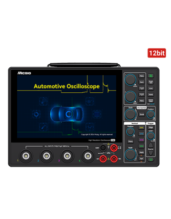
The Micsig AHO1 Series is a professional high-resolution automotive oscilloscope designed for advanced vehicle diagnostics. It features a 12-bit ADC, 200 MHz bandwidth, 4 analog channels, a 1 GSa/s real-time sampling rate, and 110 Mpts memory depth, delivering accurate and reliable measurements for automotive workshops and technical laboratories.

Its ultra-slim 3.1 cm portable design, integrated high-capacity lithium-ion battery, and USB Type-C charging capability make it ideal for mobile diagnostics and on-site maintenance operations.

With its innovative dual software architecture for automotive and general-purpose applications, along with dedicated testing modes for engines, sensors, actuators, and EV systems, the AHO1 Series supports diagnostics for both internal combustion and new energy vehicles.


Technical Specifications

  • Bandwidth: 200 MHz
  • Analog Channels: 4
  • Real-Time Sampling Rate: 1 GSa/s
  • Rise Time: ≤ 1.75 ns
  • Memory Depth: 110 Mpts
  • Vertical Resolution: 12-bit
  • Waveform Capture Rate: up to 50,000 wfms/s
  • Interfaces: USB 3.0 Host, USB Type-C, LAN, HDMI
  • Display: 8" TFT LCD capacitive touchscreen, 1280 × 800 pixels
  • Battery: 3.7 V, 16000 mAh lithium-ion battery
  • Power Supply: DC 12 V adapter and Type-C 5 V charging
  • Multimeter Accuracy: 4⅚ digits
  • Dimensions: 265 × 174 × 31 mm