


Reference :
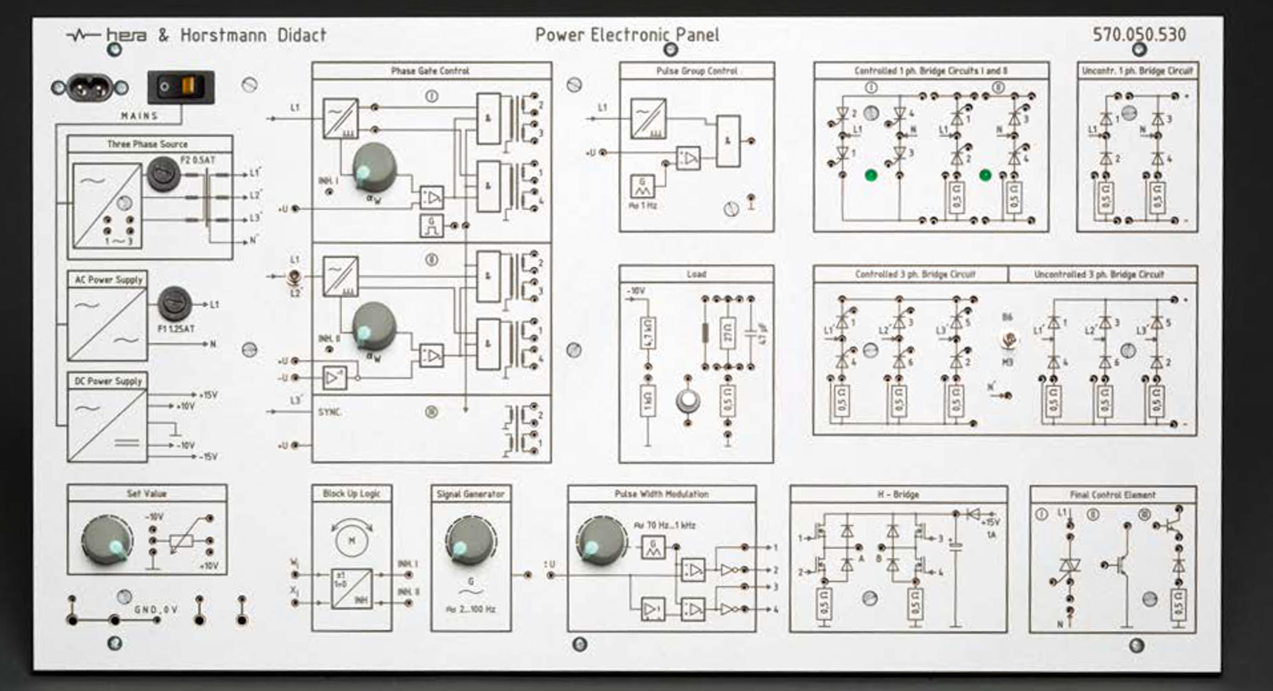
The Power Electronics Panel is a compact training system designed for performing experiments in power electronics on DC, single-phase AC, and three-phase AC circuits using a safe low-voltage approach.
The panel includes integrated resistive, inductive, and capacitive loads, enabling a comprehensive understanding of power electronics behavior and applications.
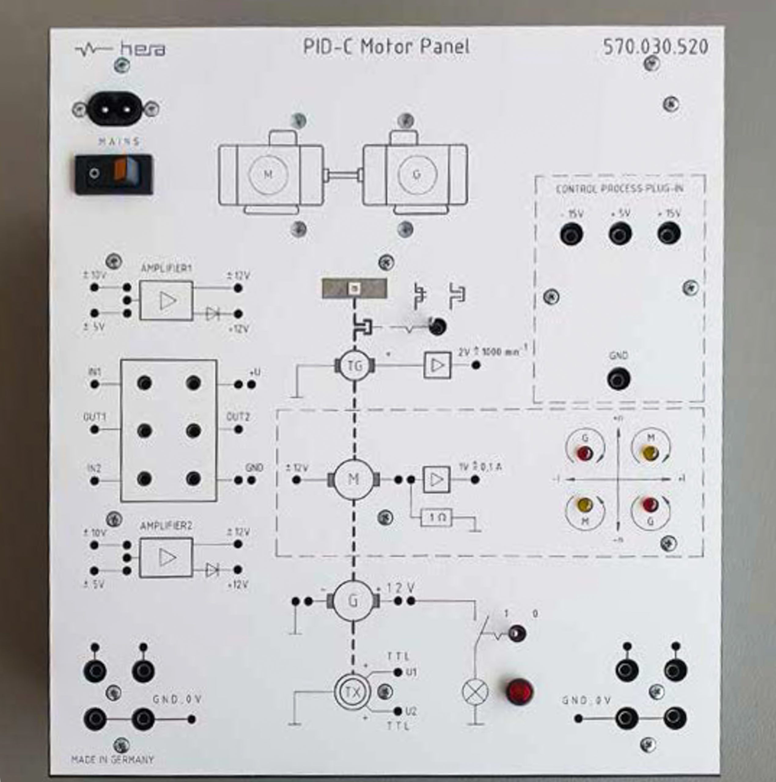
An optional motor/generator module can be added to extend the system capabilities to electromechanical and control system applications.
Overview
The motor panel can be used in combination with the main panel for advanced control and electromechanical experiments.
Learning Content (with main panel)
Specifications
An oscilloscope is required to perform experiments.


![]()
Reference : 8200388 - Servo Motor Control Technology TP1421
The TP1421 training system provides a flexible, safe, and industry-oriented learning environment for servo motor and stepper motor control technology. This comprehensive solution enables learners to develop practical skills in installation, configuration, commissioning, maintenance, and troubleshooting of industrial drive systems.
The training package is based on the “Servo Motor Control” course, available either as a digital course through Festo LX or as a practical workbook. The learning activities combine theoretical knowledge with hands-on applications to strengthen the technical and operational skills of automation specialists, industrial electricians, maintenance technicians, and electrotechnicians.
Learners gain practical experience in the following areas:
Reference :
The Power Electronics Panel is a compact training system designed for performing experiments in power electronics on DC, single-phase AC, and three-phase AC circuits using a safe low-voltage approach.
The panel includes integrated resistive, inductive, and capacitive loads, enabling a comprehensive understanding of power electronics behavior and applications.
An optional motor/generator module can be added to extend the system capabilities to electromechanical and control system applications.