
- New

Reference : FM-100.09E
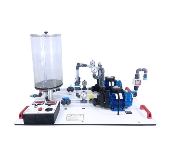
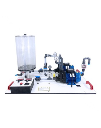
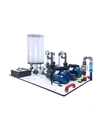
The FM-100.09E is a hydraulic training system designed for practical teaching in fluid mechanics and the study of pump performance. It enables students to investigate the operation of two pumps individually and in series and parallel configurations.
With its closed-loop hydraulic circuit, integrated instrumentation and control console, the system allows students to perform measurements, establish characteristic curves and experimentally analyse the main operating parameters of a pump.
The FM-100.09E enables practical experiments covering:
Experiment 1 – Head-Flow Relationship
This experiment enables students to experimentally investigate the relationship between the total head and flow rate delivered by a pump. The measurements can be used to establish the pump’s head-flow characteristic curve and analyse its behaviour under different operating conditions.
Experiment 2 – Determination of Specific Speed
This experiment enables students to determine the specific speed of a pump experimentally. The resulting value can be used to characterize the type of impeller associated with the pump.
Experiment 3 – Pump Efficiency
Students can determine the pump efficiency from measured hydraulic and electrical parameters. The experiment also provides an opportunity to investigate the main factors affecting pump performance and efficiency.
Experiment 4 – NPSH Study
This experiment introduces the fundamental principles of NPSH (Net Positive Suction Head) and allows students to investigate the relationship between available NPSH (NPSH(A)) and required NPSH (NPSH(R)), as well as pump suction conditions.
Experiment 5 – Two Pumps in Series
Two identical pumps can be configured in series to experimentally investigate the effect of this arrangement on head and flow rate. Measurements can be used to determine and analyse the resulting characteristic curve.
Experiment 6 – Two Pumps in Parallel
Two identical pumps can also be configured in parallel. This experiment allows students to investigate the effect of the parallel configuration on flow rate and head and to experimentally determine the corresponding characteristic curve.
The FM-100.09E features a closed-loop hydraulic circuit with an integrated water tank. This configuration allows experiments to be performed without requiring a permanent external water supply.
Water Tank
Piping and Connections
The system incorporates two identical pumps that can be operated individually or connected in series or parallel.
Electronic Flow Meter
An electronic flow meter with display is integrated into the system to measure the water flow rate during the experiments.
Pressure Measurement
The system is equipped with five pressure gauges for measuring pressure at different points of the hydraulic circuit.
The hydraulic circuit includes five valves for circuit isolation, configuration and flow control.
This configuration allows the different operating modes required for the practical experiments to be selected and measurements to be performed under controlled conditions.
An integrated control console allows the two pumps to be controlled while monitoring their electrical consumption.
The controls and instruments are grouped on an easily accessible console to facilitate practical laboratory work.
The FM-100.09E is particularly suitable for engineering schools, universities, technical institutes, vocational training centres and educational laboratories in the fields of fluid mechanics, hydraulics, mechanical engineering, energy engineering and process engineering.
| Specification | Value |
|---|---|
| Type | Hydraulic training system |
| Water tank | 27 L |
| Number of pumps | 2 |
| Configurations | Individual / Series / Parallel |
| Power per pump | 0.65 kW (0.85 HP) |
| Power supply | 220 V AC – 50 Hz |
| Maximum head | 13 m |
| Maximum flow rate per pump | 300 L/min |
| Maximum speed | 2,850 rpm |
| Flow meter | Electronic with display |
| High-flow measurement range | 120 L/min |
| Pressure gauges | 5 |
| Piping | PPRC or equivalent |
| Pipe diameter | 25.4 mm (1") |
| Ammeters | 2 |
| Hydraulic circuit | Closed loop |
With its two pumps, integrated instrumentation and multiple hydraulic configurations, the FM-100.09E provides a comprehensive platform for practical teaching in hydraulic machinery and fluid mechanics.
It enables students to connect theoretical knowledge with measured experimental results while developing their ability to analyse pump performance and understand the influence of different pump configurations.

Reference : FM-100.25 - Energy Losses in Bends and Pipe Fittings Module
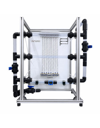
The FM-100.25 module is designed for the experimental study of pressure losses in various pipe fittings and hydraulic components. This educational system enables the analysis of the effects of direction changes, section variations, and control elements on pressure losses within hydraulic circuits.
The unit allows accurate visualization and measurement of pressure losses in several configurations, including sudden contractions, sudden enlargements, pipe bends, pipe angles, and ball valves.
The experimental unit can be easily and securely positioned on the working surface of the FM-100B base module. Water supply and flow rate measurement are provided directly by this module, ensuring simple, efficient, and reliable operation in laboratory and educational environments.

Reference : FM-100B
The FM-100B Fundamental Fluid Mechanics Training Set is a base module designed to supply various experimental units in fluid mechanics. It provides a complete educational platform featuring a closed water circuit with a storage tank, submersible pump, and measuring tank.
This system is ideal for engineering laboratories and technical training environments, enabling hands-on experiments and accurate analysis of hydraulic phenomena, including volumetric flow rate measurement and flow behavior.
The FM-100B unit supports the following experimental modules:

Reference : FM-100.04
Flow rate measurement is a fundamental aspect of measurement technology. The FM-100.04 experimental unit enables students to explore, understand, and apply various flow measurement methods in pipe systems.
Featuring transparent components and integrated measuring instruments, this unit allows direct visualization of internal processes, enhancing practical learning and comprehension of fluid mechanics principles.
This unit is ideal for:

Reference : FM-100.10
The FM-100.10 is an educational and experimental unit designed to study forces generated by fluid jets. When a flowing fluid is accelerated, decelerated, or deflected, its velocity changes, resulting in a variation of momentum and consequently producing measurable forces.
In practical engineering applications, these forces are used to convert kinetic energy into mechanical work, such as in Pelton turbines.
The unit generates a water jet directed at interchangeable deflectors. The jet is deflected at different angles, producing forces that can be measured.
The jet force is adjusted by varying the flow rate. Experiments allow investigation of:
Measured forces are compared with theoretical values calculated using the momentum equation.
The unit is designed for easy and secure placement on the FM-100B base module.
Water supply and flow rate measurement are provided by the base module. Alternatively, the unit can be operated using a laboratory water supply.

Référence : FM-151
The FM-151 is a comprehensive training system designed for the study of hydrostatics, enabling analysis of fluid behavior at rest and the effects of hydrostatic pressure. It is ideal for engineering education in fields such as plumbing, fluid mechanics, aerospace, and marine engineering.
The system allows a wide range of experiments including pressure measurement, capillarity, buoyancy, and Boyle’s law demonstration. Its transparent design ensures clear visualization of physical processes in real time.
Reference : FM-100.02
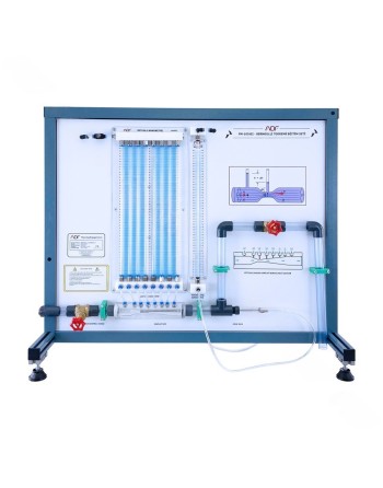
The FM-100.02 experimental unit is designed to demonstrate Bernoulli’s principle, which describes the relationship between fluid flow velocity and pressure. According to this principle, an increase in flow velocity results in a decrease in static pressure, while the total pressure remains constant. This is a direct application of the conservation of energy in fluid flow.
This educational unit is ideal for technical training and laboratory environments, enabling clear visualization and accurate measurement of pressure variations within a Venturi nozzle.
The experimental unit can be easily and securely positioned on the working surface of the FM-100B base module. Water supply and flow rate measurement are provided directly by this module, ensuring simple, efficient, and reliable operation in laboratory and educational environments.

Reference : FM-303
The FM-303 is an advanced experimental unit designed for the study of fluid mechanics, specifically focusing on incompressible air flow. It enables precise measurement of pressure distribution and velocity profiles, which are essential for turbomachinery design and fluid system analysis.
With its extensive range of accessories, the FM-303 allows a wide variety of experiments in steady incompressible flow. It is equipped with Pitot tubes for analyzing both free jets and internal pipe flow.
A low-loss inlet and optimized pipe section ensure ideal flow formation. Air flow can be analyzed using interchangeable elements such as a nozzle, orifice plate, or adjustable iris diaphragm.

Référence : FM-100.12
The FM-100.12 experimental unit is designed for the detailed study of pressure losses in pipes under both laminar and turbulent flow conditions. During fluid flow through pipes, pressure losses occur due to internal fluid friction as well as friction between the fluid and the pipe wall.
This unit enables the determination of the friction factor, a dimensionless parameter essential for calculating pressure losses. The friction factor is closely related to the Reynolds number, which represents the ratio of inertial forces to viscous forces.
The system allows analysis of the relationship between pressure loss and flow velocity, as well as experimental determination and comparison of friction factors with theoretical values.
The unit includes a small-diameter pipe section where both laminar and turbulent flows can be generated. The Reynolds number and friction factor are determined based on measured flow rate and pressure losses.
In turbulent flow conditions, the pipe is directly supplied from the water network. For laminar flow, a constant pressure is maintained using a standpipe with overflow. Flow rate is controlled using valves.
Reference : FM-230- Flow Through Pipes and Fittings Training System
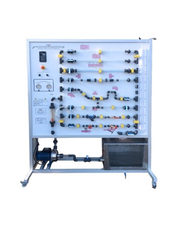
The FM-230 training system is designed for the experimental study of head losses in pipes and hydraulic fittings. This educational unit enables students and technicians to analyze fluid behavior in different piping systems, evaluate pressure losses, and study the hydraulic characteristics of valves and pipe components.
The equipment is particularly suitable for fluid mechanics laboratories, applied hydraulics, process engineering education, and technical training centers.

Reference : FM-204
The FM-204 is a training unit designed for the comprehensive study of pressure losses in piping systems. It enables the visualization and analysis of hydraulic resistance effects caused by pipe elements such as elbows, valves, and cross-section variations.
With its modular design and interchangeable components, this system is ideal for technical and higher education laboratories.
When water flows through a piping system, hydraulic resistances lead to pressure losses, particularly at fittings, valves, and other pipe components.
The FM-204 unit is designed to study and visualize these pressure losses in various piping elements. This experimental setup enables the analysis of how different pipe geometries influence fluid flow.
The FM-204 experimental unit consists of a pipe section incorporating several elements with different flow resistances, as well as contraction and expansion sections. A ball valve is also integrated into the system.
Pressure measuring points equipped with annular chambers are positioned upstream and downstream of the pipe elements to ensure accurate pressure measurements.
These measuring points can be connected in pairs to six tube manometers, allowing the determination of pressure losses across each piping element.
- Study of major and minor pressure losses
- Flow analysis in different materials and pipe diameters
- Understanding pressure and flow behavior
- Practical training in measurement and instrumentation
- Fluid mechanics laboratory experiments

Reference : FM-150.08 - Bernoulli’s Theorem and Flow Measurement
Overview
The training unit is designed to demonstrate Bernoulli’s theorem and to perform flow measurement calculations using a variety of flow measurement devices.
Features
This self-contained system includes its own storage tank, integrated pump, and support frame, allowing it to operate independently without the need for external equipment.

Référence : FM-100.08
The FM-100.08 is an experimental unit designed for the comprehensive study of centrifugal pumps. This turbomachine enables users to understand fluid transport principles and to record typical pump characteristic curves.
The unit includes a self-priming centrifugal pump, a ball valve on the outlet side, and manometers on both inlet and outlet sides. It is powered by an asynchronous motor with continuously adjustable speed via a frequency converter.
The experimental unit can be easily and securely positioned on the working surface of the FM-100B base module. Water supply and flow rate measurement are provided directly by this module, ensuring simple, efficient, and reliable operation in laboratory and educational environments.
Reference : DM-102
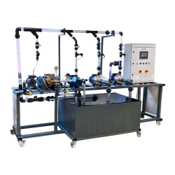
The DM-102 Pump Variations Training Set is a comprehensive educational system designed for the study and analysis of various pump types and their operating principles.
Centrifugal pumps
Two centrifugal pumps allowing individual, series, or parallel operation.
Piston pump
Positive displacement pump for controlled flow experiments.
Side-channel pump
Self-priming, capable of handling gases depending on liquid level.
Each pump is driven by a three-phase AC motor. Speed control is achieved via frequency converters.
One free position with reversible motor allows integration of additional pumps.
Reference : FM-100.25C - Pressure Losses in Piping Systems
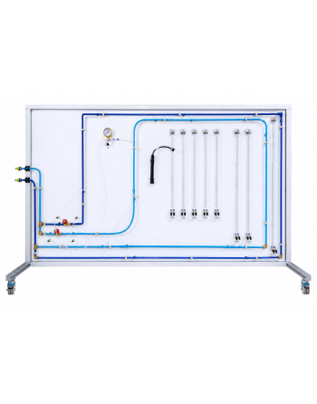
The FM-100.25C module is designed for the analysis and investigation of pressure losses in piping systems and hydraulic components. It enables the visualization and measurement of pressure variations generated by different pipe elements, making it an ideal educational solution for fluid mechanics, hydraulics, and process engineering laboratories.
The system allows the study of pressure losses caused by various piping components and flow control elements, including:
Integrated annular chambers ensure accurate static pressure measurements at different points of the hydraulic circuit.
Reference : FM-100.07
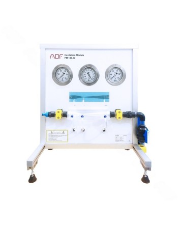
The FM-100.07 is an educational unit designed to demonstrate cavitation phenomena in fluid systems. Cavitation occurs when the static pressure drops to the vapor pressure due to increased flow velocity, leading to the formation of vapor bubbles.
These bubbles collapse when pressure rises again, making the process observable and measurable.
The experimental unit can be easily and securely positioned on the working surface of the FM-100B base module. Water supply and flow rate measurement are provided directly by this module, ensuring simple, efficient, and reliable operation in laboratory and educational environments.

Reference : FM-100.03
The FM-100.03 - Osborne Reynolds Experiment is a didactic training unit designed to clearly demonstrate the flow characteristics of liquids. It enables the visualization of laminar and turbulent flow regimes through a vertical representation of flow lines.
Reference : FM-100.09E
The FM-100.09E is a hydraulic training system designed for practical teaching in fluid mechanics and the study of pump performance. It enables students to investigate the operation of two pumps individually and in series and parallel configurations.
With its closed-loop hydraulic circuit, integrated instrumentation and control console, the system allows students to perform measurements, establish characteristic curves and experimentally analyse the main operating parameters of a pump.
The FM-100.09E enables practical experiments covering:
Experiment 1 – Head-Flow Relationship
This experiment enables students to experimentally investigate the relationship between the total head and flow rate delivered by a pump. The measurements can be used to establish the pump’s head-flow characteristic curve and analyse its behaviour under different operating conditions.
Experiment 2 – Determination of Specific Speed
This experiment enables students to determine the specific speed of a pump experimentally. The resulting value can be used to characterize the type of impeller associated with the pump.
Experiment 3 – Pump Efficiency
Students can determine the pump efficiency from measured hydraulic and electrical parameters. The experiment also provides an opportunity to investigate the main factors affecting pump performance and efficiency.
Experiment 4 – NPSH Study
This experiment introduces the fundamental principles of NPSH (Net Positive Suction Head) and allows students to investigate the relationship between available NPSH (NPSH(A)) and required NPSH (NPSH(R)), as well as pump suction conditions.
Experiment 5 – Two Pumps in Series
Two identical pumps can be configured in series to experimentally investigate the effect of this arrangement on head and flow rate. Measurements can be used to determine and analyse the resulting characteristic curve.
Experiment 6 – Two Pumps in Parallel
Two identical pumps can also be configured in parallel. This experiment allows students to investigate the effect of the parallel configuration on flow rate and head and to experimentally determine the corresponding characteristic curve.